Contact Form


Understanding Quality of Service


What is QoS?

QoS or Quality of Service is a feature present in switches and routers that help prioritize certain types of traffic over other types of traffic. QoS in essential to any organization’s network traffic and plays a significant role when it comes to real-time traffic (voice and video).
Computer networks at first simply put were meant to transport data from point A to point B. As time passed by computer networks grew larger and larger, the types of protocols traversing through these networks were simultaneously growing. On the other hand, networks started converging and technologies like voice and video conferencing evolved from being on their own individual platforms to reside with IP traffic. There was no real way of prioritizing and segregating traffic until QoS came into the picture. With the help of QoS we could potentially apply various policies onto our traffic that act differently for different types of data. To understand the need for QoS let us first differentiate the various characteristics of traffic.

Characteristics of traffic

Traffic making its way across a network behave differently depending on the protocols used by applications. In general, traditional traffic traversing the network is in large bursts. Traffic followed the FIFO (First In First Out) i.e. traffic arriving first on a switchport would be the first to be serviced by the switch. Data traffic (like http or ftp) were not sensitive to delays and delays as such were acceptable. In case of any drops in packets, the dropped packets could easily be checked and resent using TCP retransmits.
As networks converged and grew various other traffic characteristics started becoming apparent. For example voice traffic behaves completely different from traditional traffic and has its own individual characteristics. Voice traffic is sent out in constant short bursts and thus are in a constant fight with traditional bursty data. Voice packets are very sensitive to delay and drops. Also the retransmission of voice traffic really doesn’t solve any purpose.
Thus all traffic should not be looked at as the same and instead should be treated differently depending on the individual traffics characteristics. The different types of traffic can be identified and treated based on certain markings or labels present in the frame and/or ip packet.

QoS markings

The IEEE 802.3p standard defines QoS markings on layer 2 frames. Three bits from the frame are used to identify a total of 8 (0 to 7) values that can be used to classify traffic. These eight values are known as COS (Class of Service) markings and used to classify traffic based on QoS on a layer 2 level
For Layer 3 based QoS classification the ToS (Type of Service) Byte of the ip header is used for QoS markings. Using this 8 bit field there are two different markings are possible. One being IP Precedence and the other being DSCP (Differentiated Service Code Point). Using the IP Precedence model up to 8 different markings are possible and using the DSCP model up to 64 different markings are possible. The various traffic types present in our network can be assigned with an appropriate CoS/DSCP value. Once this value is assigned to the traffic the traffic can be treated differently depending on the value assigned to it.
QoS is a three stage process consisting of identifying the traffic, applying certain rules to the various traffic types present and then sending it out the desired interface with the interface specific settings applied. This three step process can easily be implemented with a MQC (Modular QoS CLI) based configuration.

Modular QoS CLI

The Modular QoS mechanism is an evolution from the traditional method of QoS configuration (standard CLI). The CLI methodology is tedious as it means applying policies applicable for each interface individually. The reutilization of this code is not feasible in this method. The MQC model being modular in nature allows different sets of configuration to be used or reused differently with other sets of configuration. For Example a red Lego block can be used to build a nice little red house and that very same red block can be used to build a not so nice death ray. Similarly parts of configuration can be placed and used differently using the MQC model. The MQC configuration model consists of class-maps, policy-maps and service-policies and each of these work in tandem to provide the desired QoS settings.
Class-maps
Class-maps are used to classify or identify traffic. They consist of certain match statements and can be used with a variety of techniques (like Access Control Lists, DSCP markings, NBAR) to match traffic
Policy-maps
Policy-maps define what policies are to be applied onto the various traffic types matched by the previously defined class-maps.
Service-policy
A service-policy defines where these policies are applied. It defines whether the traffic policies are on the ingress or egress of which interface.

Auto QoS

Then came the magic of Auto QoS. A method where in a single command would automatically generate a set of QoS commands that are appropriate for a generic QoS implementation. Further modification of these rudimental settings are easily possible. With Auto QoS, deployment of QoS mechanisms became quicker and more simplified.

Total comment

Author

9_bits


Overview and Specifications

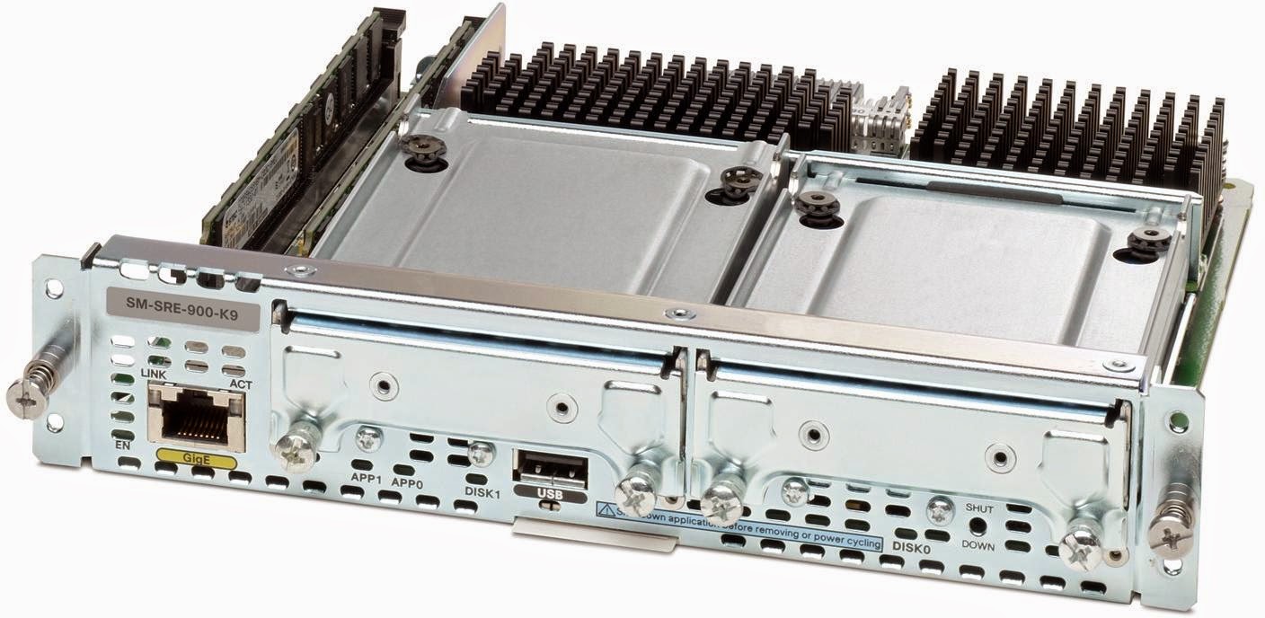
Cisco’s Services Ready Engine is an innovative and revolutionary product. It provides multiple forms of functionality, one of which is as a virtualization platform. This report briefly describes the performance capabilities of the SRE in terms of virtualizing a small branch office’s Windows 2008 server. There are various iterations of the SRE like the SRE 300, SRE 700/710 and SRE 900/910, each with their own specifications ranging from single core 1.0 GHz. processors to dual core 1.86 GHz. processors. The hard disk support goes up to 1 TB with support for RAID (0 or 1). The highest end SRE can support up to 8 GB of memory. The SRE 300 is a smaller Integrated Service Module while the SRE 700/710 and SRE 900/910 are Service modules that slot into the back of the router. The SRE’s have 3 gigabit ports that can be used. The first port available is a layer 3 port to the Routers CPU and is used mainly for configuration purposes. The second port is used to connect to a multi gigabit fabric thus providing really fast Layer 2 connectivity by bypassing the routers CPU. There is a third port external to the SRE as an external gigabit port and is controlled entirely by the hypervisor.

Test Setup

The test setup consists of an SRE 900 placed in a Cisco 2911 Router. The Router IOS running is 15.2(4)M4 and the SRE is running on SRE-V 2.0.1 The SRE 900 consists of two 500 GB HDD spinning at 5400 rpm and they are placed in RAID 0. They have a clean install of Windows Server 2008 R2 running on partitions that have been eager zeroed for performance. The SRE 900 also consists of 4 GB of ram adequate enough to handle Windows Server 2008 R2. The SRE 900 comes with an Intel Core 2 Duo Processor, the L9400. The L9400 is a dual core processor with both cores unlocked (unlike the SRE700/710’s single unlocked core). The processor is based on Intel’s 45nm process comes with 6 MB of L2 Cache and has a 64 instruction set thus allowing full use of the 4 GB of ram present. To test the three most critical components of any server’s performance I have included graphs of the Processor, Memory and HDD utilization. The test consisted of the initial boot up (Between 10:40 and 10:50), the idle state (10:50 – 11:10), the high load state (11:10 – 11:40) and back to the idle state (11:40 – 11:50). During the idle states no application was allowed to run and the system was left untouched. In the high load state I had installed and ran multiple Windows Server 2008 roles (DNS, DHCP, RDP, File Services etc.)

Benchmarks

C:\Users\Neelesh\AppData\Local\Microsoft\Windows\INetCache\Content.Word\CPU2.jpg
C:\Users\Neelesh\AppData\Local\Microsoft\Windows\INetCache\Content.Word\CPU.JPG
C:\Users\Neelesh\AppData\Local\Microsoft\Windows\INetCache\Content.Word\Disk.jpgC:\Users\Neelesh\AppData\Local\Microsoft\Windows\INetCache\Content.Word\Disk2.jpgC:\Users\Neelesh\AppData\Local\Microsoft\Windows\INetCache\Content.Word\Memory23.jpg

Conclusion

Generally on startup and boot up, the SRE performed very well. The time for SRE-V to boot up was 3 minutes 10 seconds and the time for SRE-V to shutdown was 24 sec
Time for Win 2k8 to boot up to login screen on a clean configuration takes 38 seconds and from boot up till the desktop it takes just under a minute. Shutdown takes 7 seconds.
Looking at the CPU charts the SRE doesn’t seem to have a high load on the CPU during the startup of the system and remains constant during idle times. During heavy utilization the CPU spikes to 2 GHZ. Which is around half the capacity of the processor.
Hard disk utilization is also not that high and maxed out to 7.5MBps this is probably due to the disks being in RAID 0 and eager zeroed. The seek times were also always under 20 Milliseconds.
Memory requirements did remain a constant throughout the idle stage. However the SRE-V overshadowed the available memory by occupying a large chunk of memory (about a gigabyte). Under heavy loads the memory was completely used up but this was mainly because of the multiple services running at the same time. The memory drops down to a significantly lower value after a small amount of time.
In my opinion the SRE is an amazing product that can bring server functionality to the router. The SRE can easily be used on small branch offices for a light/medium workload. On a larger site or a site with a lot of users the SRE tends to do more harm than good due to its inability to match the performance benefits of a server.

Total comment

Author

9_bits

A VoIP primer


Well VoIP had a long and eventful journey before it became what it is today. Let’s first try to put together a bit of history to understand how it got to where it is today.

History

Well the first notable piece of history can be looked at as Thomas Edison’s invention of the phonograph. This rudimentary device allowed for a user to record his voice onto a piece of tin foil. The indentations made by this device could then be used to playback the recorded sound. The first form of telephony took place with the help of analog lines. Analog telephony used the properties of electricity to represent human speech. Apart from speech analog telephony used electricity to send signals across. These signals were used to indicate if a phone was busy or if dial-tone should be provided for example. An analog circuit consisted of a pair of wires one being the tip (connected to the ground) and the other being the ring (connected to the battery). A -48V DC current would be provided by the service provider side. These tip and ring combinations along with the combination of power being provided from the CO allowed for the phone to send signals. When the phone was placed on hook there would be an open circuit thus not allowing the current to flow through. This in turn would inform the central office that the phone is on hook. When the phone would go off hook the circuit would be connected and thus current would flow through indicating that the phone was off-hook. This form of signaling was known as Loopstart signaling.


There is another form of signaling known as Ground start signaling. Ground start signaling was formed to alleviate the issues caused by Loop start signaling. With loop start signaling there was an issue caused known as glare. Glare occurs when the user picks up his phone the same time an incoming call occurs causing the incoming call to be received by the wrong user. Ground start eradicated glare by grounding wires to signal for dial-tone.


Analog communications withstood the years but was eventually overcome by a need for a newer form. Analog signals while passing through a wire were subject to a loss in quality as they travelled large distances. To circumvent this issue repeaters were placed along the path however the repeaters would inadvertently amplify not only the voice but also the noise generated along the path. Another issue that came up was the number of wires that were required to be laid out by the service provider in order to connect all its users. It was time for analog to grow out of itself and evolve into something new. This came in the form of digital communication. 

Digital Communication

Digital communication involves the conversion of analog signals into an equivalent binary value. This binary value can then be sent through a TDM (Time-Division Multiplexing) circuit. TDM allowed multiple pieces of information to flow using the same single line. This eliminated the issues caused by analog communication. The number of wires reduced as a single line could be used instead of multiple lines. The signals being in binary were easily recreated at the receivers and thus eliminated the need for repeaters.
Digital communication can come in two cabling mechanisms T1 or E1. T1 is a cabling mechanism used in the United States, Canada and Japan. This T1 line allowed for up to 24 different channels of communication with a single wire. An E1 circuit is used in countries other than North America and Japan. An E1 line consists of 32 channels. These channels are called DS0’s (Digital Signal 0). Each of these DS0’s can transmit at 64 kbps. Each of these cabling mechanisms can transmit data using one of two methods CAS (Channel Associated Signaling) or CCS (Common Channel Signaling). CAS involves a procedure wherein signaling is sent along with the individual channels. In CCS a channel is dedicated purely for signaling.
CAS allows for the first 5 frames of each channel through as it is. The sixth frame has the last bit from each channel used for signaling. This would cause a slight degradation in voice quality but nothing too significant for the user to notice. In the case of a T1 CCS the 24th channel is used for signaling while in an E1 CCS the 16th channel is used for signaling.

Understanding Key systems and PBX

These T1/E1 lines were used with systems known as PBX (Private Branch eXchange) or key systems. These lines connected the systems with the PSTN (Public Switched Telephone Network) to make outbound calls across the world. These systems were similar to Central Office switches and basically connected multiple phones together within an enterprise environment. Key systems are a smaller implementation of a PBX. It supported fewer users and didn’t have all the features a PBX could offer. These systems were quite resilient and would have an uptime of 99.999% and a lifespan of 7 – 10 years. They were made of three components
Line cards – Used to connect phones present in the network with the PBX
Trunk cards – Used to connect one PBX to either the PSTN or another PBX
Control Complex – The brains of the whole operation. It decides on how calls are routed and setup.
Well we moved up from analog to digital communication and now let us understand why there was a need for a new more improved technology in the form of VoIP.
Benefits of VoIP
Cost – The first thing on everyone’s mind is cost. A factor by which every decision is made. And this is one of the most significant features of VoIP. Instead of paying the PSTN operator for calls between branches with VoIP you can send the call through the existing WAN connection between the sites. Reducing not only the call cost but also the need for any T1/E1 lines. MACs (Moves Adds and Changes) are significantly cheaper with a VoIP based system. Instead of running separate cables for both voice and data a single cable is required thus reducing cabling costs.
Portability – VoIP communications make use of softphones or even hard phones to allow you to literally take your phone with you. You can take your phone home and it would function the same as it did in the office.
Rich unified media – VoIP brings with an ecosystem where e-mail, conferencing, voicemail, voice and video all coexist in a single environment. Thus
Productivity – The features provided with voice based communications can allow users to communicate effectively and efficiently.
Open standards – With the help of open standards like SIP multi-vendor implementations are easily possible, opening up a window of choices for the enterprise.

The process of converting voice to packets


Now that we took a small history lesson into how we ended up with VoIP, let’s try to understand how a voice gets converted to a packet.
As you speak into a telephone our voice gets converted to analog in the form of electrical signals. Analog communication can be represented using a waveform like the one below.
The amplitude is measured on a scale of +127 to -127. These analog signals can be sampled to create equivalent values that represent the value of the amplitude at a particular time. How many samples need to be taken can be determined by a theorem postulated by Dr. Harry Nyquist. It was known as the sampling theorem and stated that to accurately represent an analog signal we have to sample at twice the highest frequency. Taking the highest frequency as 4000 Hz. We should take at 8000 samples per second (4000Hz. X 2). Each sample can be represented with a single byte. The first bit of the byte is used to represent the positive or negative scale and the next 7 bits (2^7 = 128) are used to represent the actual value.
Voice at this point has been digitized. If we calculate the bandwidth required we end up with 64 kbps (8 bits X 8000 samples/second). This conversion mechanism converts our voice into the G.711 PCM standard. There are various methods or mechanism in place to further reduce this bitrate. For example, G.729 codec consumes only an eight of the bandwidth (8 kbps). Various implementations of codecs exist each having their own advantages and disadvantages. One such example is the G.722 codec. Even though it uses the same bandwidth consumed by the G.711 codec (64 kbps) it produces noticeably better audio quality as it captures a wider range of frequencies.

Total comment

Author

9_bits